
KENCAD User Manual
Version: KENCAD 1.0.13
Target Audience: First-time users of CAD, rebar reinforcement, or fabrication ledger software.
Figure Descriptions: All interface images in this document are taken from the actual desktop application. Colored frames, highlights, arrows, and numbering are used to indicate the specific areas to focus on for each step.
1. What KENCAD Can Do For You
KENCAD is a desktop software suite for structural reinforcement engineering. It integrates CAD drafting, engineering data reading, component reinforcement, cutting list calculation, and fabrication ledger management into a single application. It is ideal for the following scenarios:
| Use Case | Task Description | Recommended Entry Point |
|---|---|---|
| View or modify CAD drawings | Open DXF, DWG, etc., to draw, edit, annotate, and plot | Top "File", "Draw", "Annotate" |
| Create beam reinforcement from design drawings | Retain original geometry, clean irrelevant elements, capture supports and spans, then configure reinforcement | Top toolbar "Capture Structure → Beam" |
| Reinforce columns, slabs, walls, and footings | Select component boundaries in the drawing and enter the corresponding reinforcement workstation | Dropdown menu next to "Capture Structure" |
| Import engineering data | Read PDF, images, DXF, DWG, JWW, SFC, P21, etc., for manual verification | "File → Import Engineering Drawings" |
| Manually create fabrication ledgers | Record steel reinforcement details by site, floor, zone, and fabrication method | Top toolbar "Fabrication Ledger" |
| Generate fabrication ledgers from CAD | Select elements with rebar data in the canvas to enter the ledger editor directly | Ledger List "Select CAD Elements" |
| Import existing fabrication data | Restore fabrication ledger files or import ATS, CAD summaries, and BBS data | Bottom tool area of the Ledger List |
| Output production documents | Output weight tables, cutting lists, fabrication summaries, tag cards, CSV, PDF, and Excel | F6–F12 in Ledger List or editor bottom |
Business data is stored locally. When production fields are incomplete, the screen lists the missing fields and output remains unavailable until they are filled in.
2. First Time Opening the Software
When using the software on a new computer for the first time, an authorization page may appear. Enter your acquired license key and click "Activate"; the machine code is used to identify the current device. If authorization reading or activation fails, the reason will be displayed on the page. If you cannot enter the workspace, please provide the machine code and error message to your administrator.
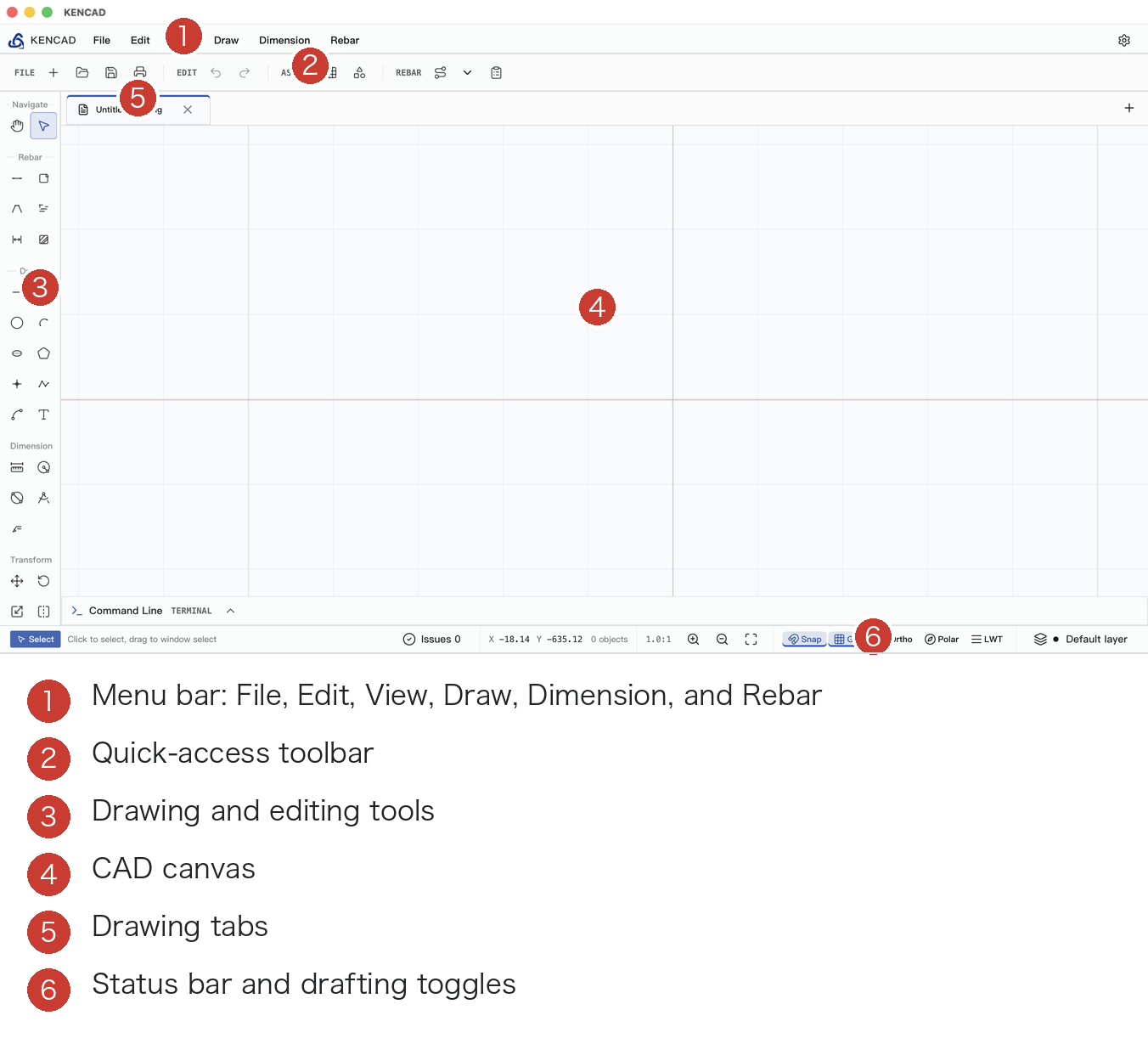
The numbers correspond to the following areas: ① Top Menu, ② Common Toolbar, ③ Drawing Tabs, ④ Left Toolbar, ⑤ CAD Canvas, ⑥ Command Line and Status Bar.
The main interface is divided into six areas:
- Top Menu: File, Edit, View, Draw, Annotate, Rebar, and Settings (top right).
- Common Toolbar: New, Open, Save, Print, Undo, Redo, Grid/Axis, Rebar Shape Library, Capture Structure, Fabrication Ledger.
- Drawing Tabs: One tab for each open drawing; a blue dot indicates unsaved changes.
- Left Toolbar: Pan, Select, Rebar, Draw, Annotate, Transform, and Edit tools.
- Central Canvas: Area for viewing, selecting, drawing, and editing CAD elements.
- Bottom Command Line and Status Bar: Displays command prompts, coordinates, object count, scale, snaps, grids, orthomode, polar tracking, lineweight, and current layer.
2.1 New, Open, and Save
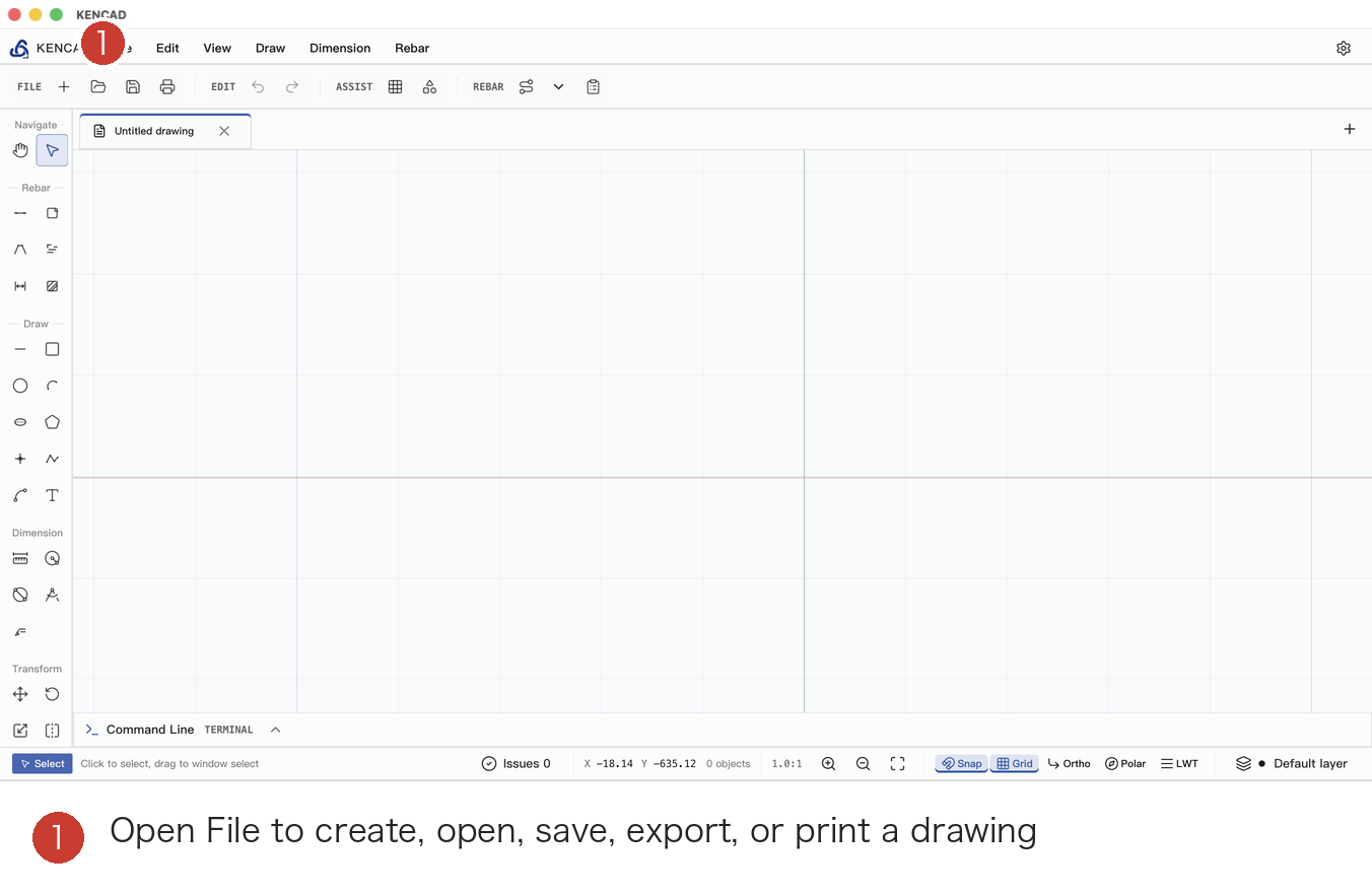
- New: Click the "+" icon on the toolbar, or use Ctrl/Cmd+N.
- Open: Click the folder icon, or use DCtrl/Cmd+O**.
- Save: Click the floppy disk icon, or use Ctrl/Cmd+S.
- Close Drawing: Click the "×" on the drawing tab. If there are unsaved changes, a confirmation appears before closing.
- Multiple Drawings: Click the "+" on the far right of the tab bar to create a new tab; click different tabs to switch between drawings.
2.2 Export and Print
Open "File → Export" to choose from:
- DWG: For further editing in DWG-compatible CAD software.
- DXF: A universal CAD exchange format.
- PNG: Export the current graphic as an image.
- Print: Select paper size, orientation, scale, and print area to print or save as PDF.
2.3 Basic Canvas Operations
- Pan: Select the "Pan" hand tool from the left toolbar and drag the canvas.
- Select Objects: Use the Select tool to click; hold Shift to add objects to the selection.
- Zoom: Use the mouse scroll wheel; the current scale is displayed in the status bar.
- Zoom Extents: "View → Zoom Extents".
- Reset View: "View → Reset View".
- Exit Current Command: Press Esc.
- Complete Continuous Pointing: Press Enter or Space.
- Undo Last Point: Press Backspace/Delete.
3. CAD Drafting and Editing
3.1 Drawing Tools
The "Draw" tool on the left or top menu provides:
| Tool | Purpose | Common Command |
|---|---|---|
| Line | Draws a line between two points | L |
| Rectangle | Draws a rectangle using two diagonal points | R / REC |
| Circle | Specifies center and radius | C |
| Arc | Creates an arc via prompt points | A |
| Ellipse | Specifies center and major/minor axes | EL |
| Polygon | Generates a regular polygon | POL |
| Point | Places a point object | PT |
| Polyline | Draws a continuous series of connected segments | P / PL |
| Spline | Draws a smooth curve through multiple control points | SPL |
| Text | Places text | T |
| Leader | Draws a line with explanatory text | ML |
The operation method is consistent: select the tool, follow the command line prompts on the canvas, use Enter/Space to finish multi-point sequences, and use Esc to exit.
3.2 Annotation Tools
The "Annotate" tool on the top or left provides:
- Linear Dimension: Annotates horizontal, vertical, or aligned distances.
- Radial Dimension: Annotates the radius of a circle or arc.
- Diameter Dimension: Annotates the diameter of a circle.
- Angular Dimension: Annotates the angle between two lines.
- Leader: Uses arrows and text to explain structural components.
3.3 Transformation and Editing
The "Transform" and "Edit" tools on the left provide:
- Move, Rotate, Scale, Mirror, Offset, Array.
- Trim, Extend, Chamfer, Fillet.
- Copy, Cut, Paste, Duplicate, Delete.
- Undo Ctrl/Cmd+Z, Redo Shift+Ctrl/Cmd+Z.
Select an object first, then execute the transformation or editing command. When parameters appear in the toolbar, enter the required values as prompted.
3.4 Snaps, Grids, Ortho, and Layers
- Snap: Automatically snaps to endpoints, midpoints, centers, intersections, etc.
- Grid: Displays an auxiliary grid.
- Ortho: Restricts movement to horizontal or vertical directions.
- Polar: Provides directional assistance at specific angles.
- Lineweight: Toggles the display of actual line weights.
- Layers: The layer panel on the right allows for creating, searching, switching, toggling visibility, locking/unlocking, and deleting layers. Default layers cannot be deleted.
3.5 Grid/Axis Generation
Click "Grid/Axis" in the top toolbar, enter the number of horizontal and vertical axes, spacing, and numbering, then generate.
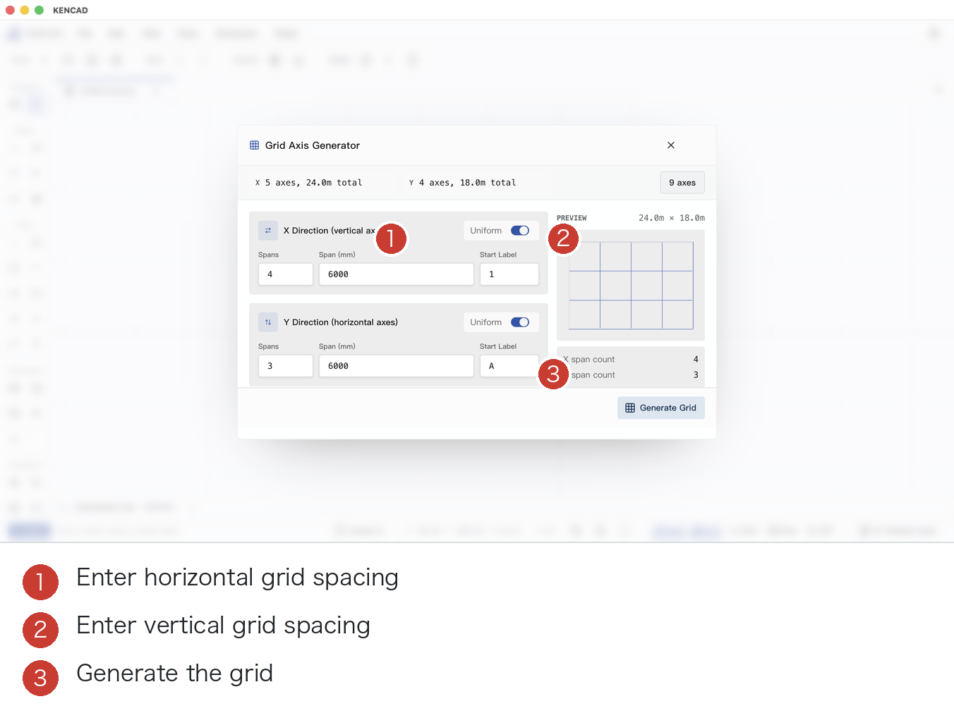
Numbered items: ① Horizontal and vertical axis parameters, ② Live preview, ③ "Generate Grid/Axis".
Once generated, the axis grid becomes a savable, selectable CAD object used for component positioning or reinforcement templates.
3.6 Command Line and Help
The "Command Line" at the bottom allows direct entry of commands like L, REC, C, PL, M, TR, DIM, etc. Press F1 or type ? in the command line to open KENCAD Help, which includes quick start guides, drawing commands, editing commands, rebar commands, shortcuts, and "About".
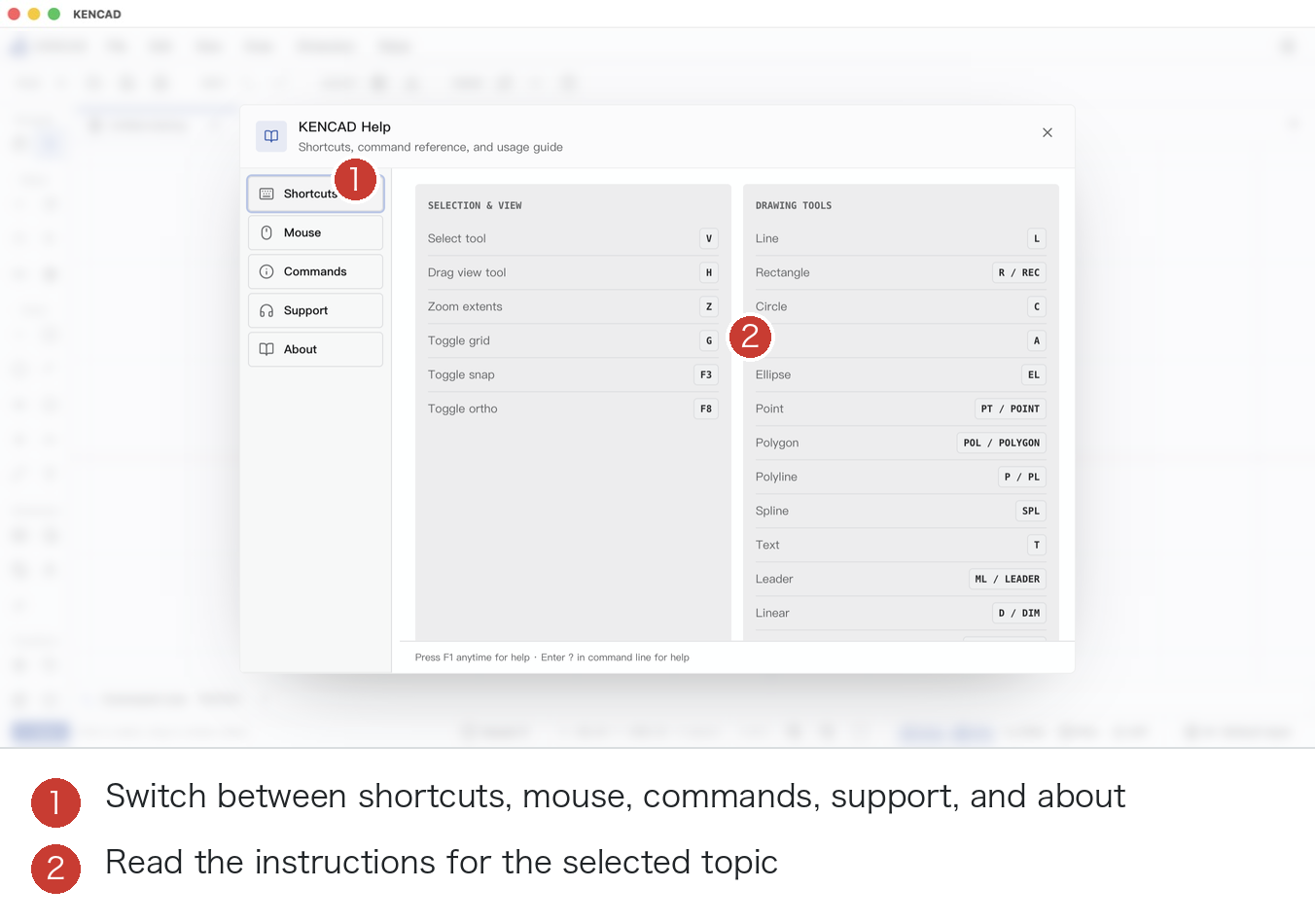
The help page features tabs for shortcuts, mouse operations, command references, technical support, and about.
4. Rebar Functions
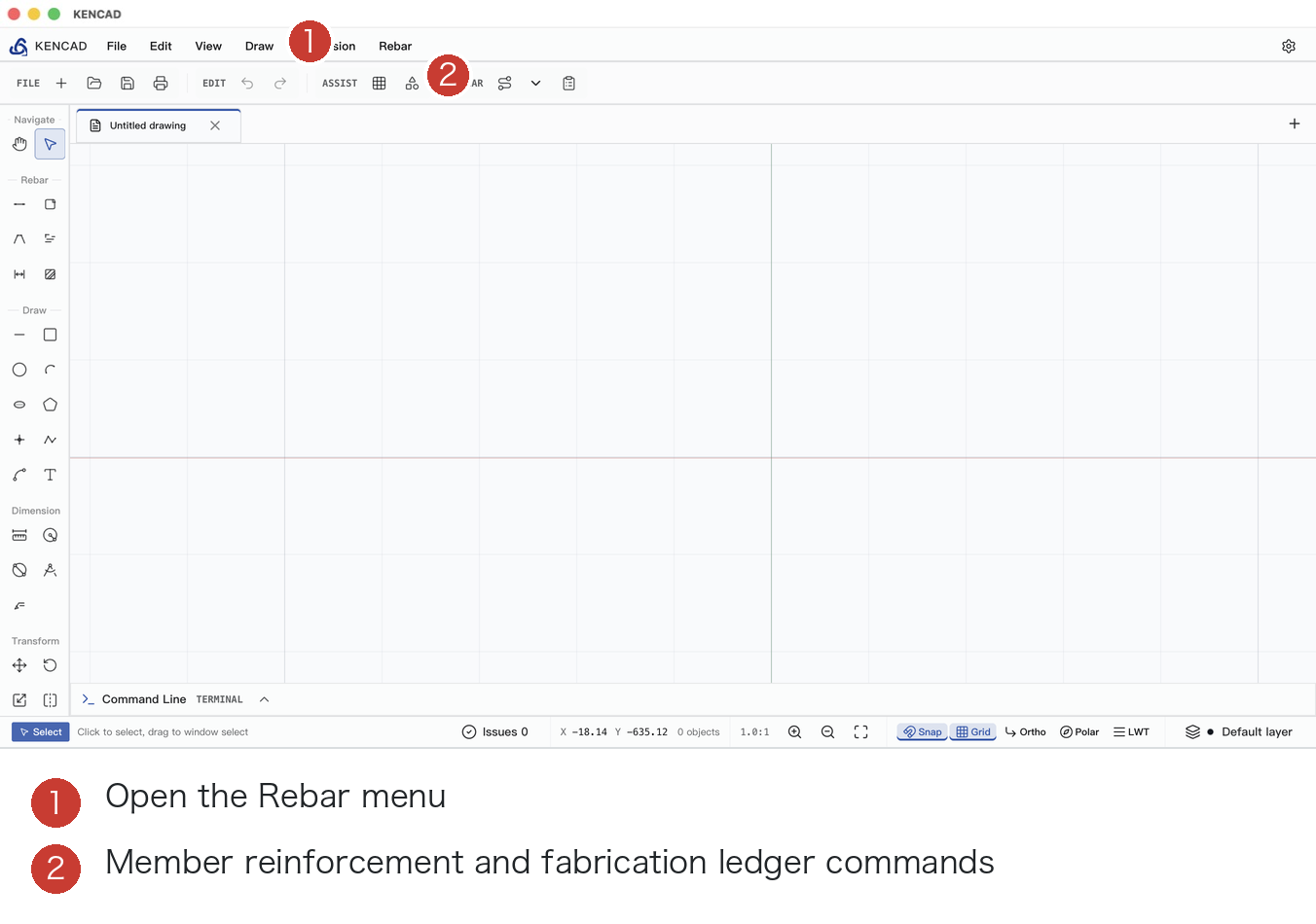
The Rebar menu integrates manual rebar, annotation, section drawings, fabrication ledgers, production workflows, and the shape library into one entry point.
4.1 Manual Rebar Tools
The "Rebar" menu provides:
- Main Bar
- Stirrup
- Bent Bar
- Rebar Annotation
- Spacing Annotation
- Section Drawing
These are suitable for cases where positions are clear and only a small amount of reinforcement needs to be placed directly on the canvas. After selecting a tool, follow the canvas prompts to pick points; the top parameter bar allows for setting material, diameter, quantity, spacing, shape, etc.
4.2 Rebar Shape Library
Clicking "Rebar Shape Library" in the top toolbar allows browsing standard shapes. The shape selection in the fabrication ledger editor uses the same shape data.
The library supports filtering by ID, Name, Label, Shape Group, and Bend Count. The current standard catalog contains 639 shapes.
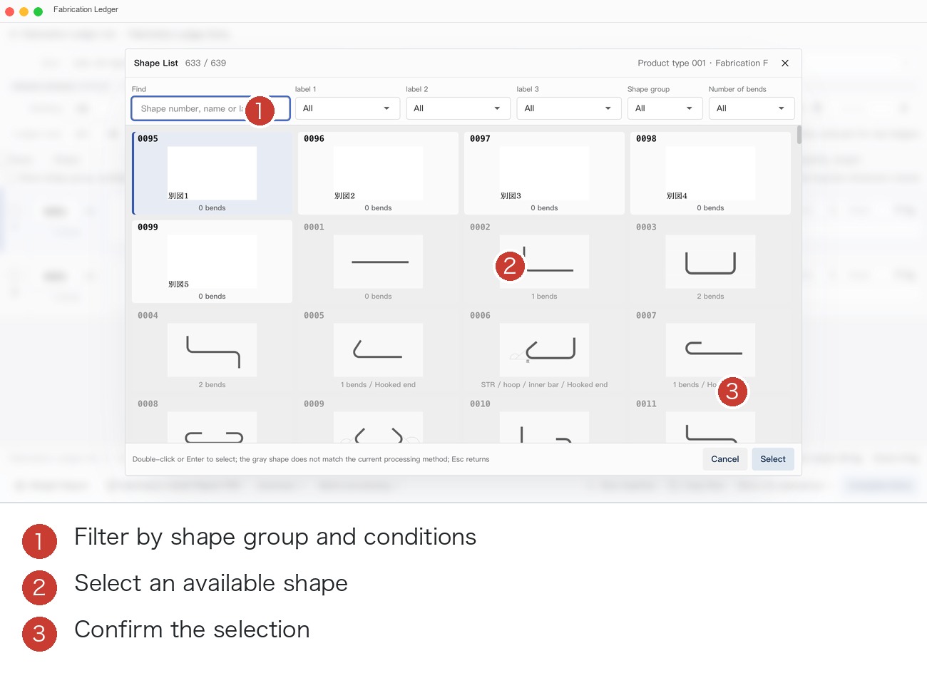
Numbered items: ① Search and filter, ② Shape preview area, ③ Selection prompt and confirmation entry.
Gray shapes indicate they are incompatible with the current material or fabrication method. Double-click a shape or select it and click "Select" to confirm; press Esc to return.
4.3 Creating Component Reinforcement from Design Drawings
The "Capture Structure" tool in the top toolbar supports:
- Beam
- Column
- Slab
- Wall
- Foundation Beam
- Foundation
Recommended Workflow for Beams
- Open the design drawing containing the beam geometry.
- Click "Capture Structure → Beam".
- Select the elements to keep, generating an independent reinforcement template.
- In cleaning mode, delete elements unrelated to that beam; the source drawing remains unchanged.
- Follow prompts to pick left and right support boundaries and span divisions, then press Enter/Space.
- Finishing the point capture opens the reinforcement workspace directly.
- In "Reinforcement Plan," configure main bars, stirrups, crank bars, tie bars, chair bars, etc.
- In "Rebar Table/Details," verify rebar lines, lengths, quantities, joints, and sources. A. In "Stirrup," set the confinement zones, non-confinement zones, first stirrup offset, and factory trimming rules.
- In "Cutting List," check cut lengths, quantities, weight, and production blocks.
- Click Writeback/Update CAD to update the formal reinforcement drawing in the current drawing.
- Enter the fabrication ledger from the "Cutting List" or export the cutting list as a CSV.
The reinforcement workstation supports switching components, copying parameters, adding similar components, deleting the current component, toggling between construction/output modes, redrawing, CAD writeback, cutting list export, and transfer to the fabrication ledger.
Reusing Adjacent Floors
- On an already completed source beam, click "Copy Parameters".
- Enter the target floor for the new beam; the target floor cannot be the same as the source.
- Enter the target drawing number, revision, or approval basis.
- Check the differences in parameters listed by the software.
- Click "Confirmed Verified".
- If parameters change again, the verification status is automatically invalidated and must be re-verified.
Copied components are saved independently; subsequent modifications to the source beam will not affect the target beam.
Columns, Slabs, Walls, and Footings
Select the corresponding component, pick the boundaries or perimeter as prompted, and enter the component name, building, floor, dimensions, and reinforcement parameters. After selection, the editor is entered directly, allowing for preview, CAD writeback, cutting list viewing, and transfer to the fabrication ledger.
5. Engineering Data Import
Entry: "File → Import Engineering Drawings".
5.1 Supported Data
- PDF and common image formats
- DXF, DWG
- JWW
- SFC, P21
- Project directories and related text data
5.2 Usage Process
- Select files or a project directory, or drag files into the selection area.
- Wait for the software to read, extract linework, and parse text locally.
- Choose a component or data page from the candidate list.
- View original linework, page numbers, building, floor, component ID, rebar, and dimension evidence.
- Manually fill in and verify production fields that lack supporting evidence.
- Items with complete information can generate CAD, add to production details, transfer to the fabrication ledger, or export the current Excel report.
- Fields with insufficient information are marked as pending; they must be completed before proceeding.
For daily beam reinforcement, prioritize the geometric fidelity workflow described in section 4.3 (deriving templates from CAD originals). Engineering data import is best for processing PDFs, images, multi-file projects, and data requiring itemized verification.
6. Production Workflow
Entry: "Rebar → Production Workflow".
This workspace is used to centrally monitor the status of engineering data as it converts into production data, including:
- Current engineering data vs. candidates.
- Missing or conflicting fields.
- Items awaiting manual verification.
- Generatable CAD and production details.
- Number of lines and status of transfers to the fabrication ledger.
- Correction plans, correction packages, and error categories.
The recommended sequence is: Select data → Complete mandatory fields → Verify fields → Generate or update CAD → Transfer to fabrication ledger → Output production documents.
7. Fabrication Ledger: Understanding Three Concepts
- Site: A construction project or site. Clients, fabrication companies, managers, and available materials are all attached to a site.
- Fabrication Ledger: A header for a specific fabrication task, containing the building, zone, floor, part, fabrication method, entry date, and arrival date.
- Fabrication Line: Each type of reinforcement within a ledger, containing shape, dimensions, rebar number, grade, material, diameter, cut length, quantity, remarks, and weight.
Open the "Fabrication Ledger" from the top toolbar to enter the Ledger List.
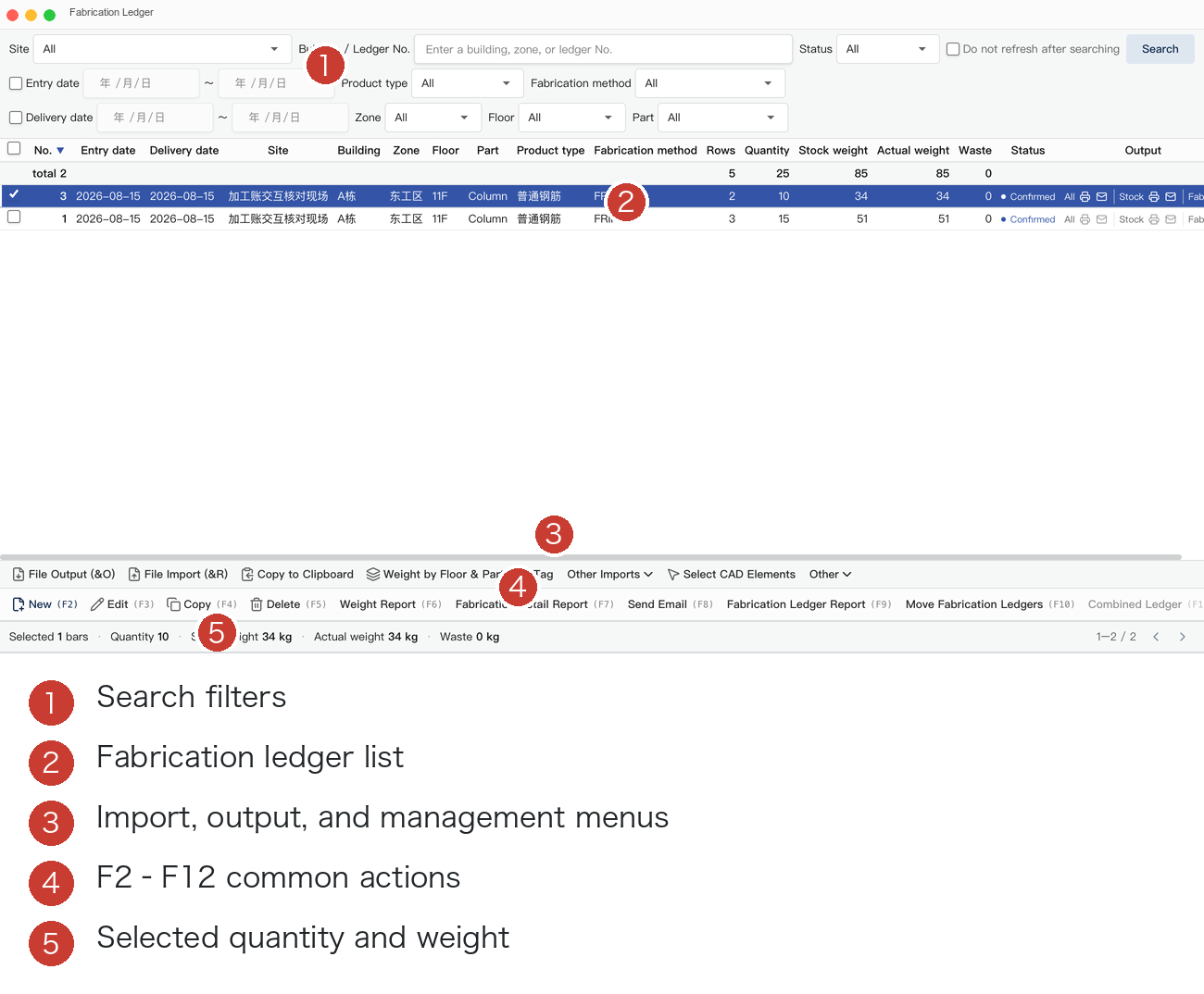
Numbered items: ① Filter and query, ② Ledger list and selection area, ③ File, Tag, and CAD direct tools, ④ F2–F12 common business operations.
8. Fabrication Ledger List
8.1 Query Area
The query area consists of three lines:
- Site, Building/Ledger No., Status, and "Do not auto-refresh after query".
- Date range for entry, grade, and fabrication method.
- Date range for arrival, zone, floor, and part.
Only the date range is included in the query if the checkbox to the left of the date is checked. Enter the criteria and click "Query". If no results are found, the page will display "No fabrication ledgers found under current query conditions".
8.2 List Fields
The table displays No., Entry Date, Arrival Date, Site, Building, Zone, Floor, Part, Grade, Fabrication Method, Line Count, Quantity, Stock Weight, Actual Weight, Loss, Status, and Output Status. Click the column header to sort; checkboxes are used for multi-selection.
The bottom status bar summarizes the selected ledger count, quantity, stock weight, actual weight, and loss.
8.3 Common Direct Tools
These entries allow for single-click access to high-frequency operations:
| Entry | Purpose |
|---|---|
| File Output (&O) | Output selected ledgers as exchange files |
| File Import (&R) | Restore fabrication ledger files and preview before writing |
| Copy to Clipboard | Copy selected data in current visible column and row order |
| Floor and Part Weight | Summarize weight by floor and part |
| Tag Card | Generate 5-part or 10-part tags, including QR codes |
| Select CAD Elements | Return to current CAD canvas to select rebar and enter the ledger |
"Other Imports" includes quantity takeoff, CAD summary, and BBS imports; "Other" includes site output, shape maps, master data/options, and history cleanup.
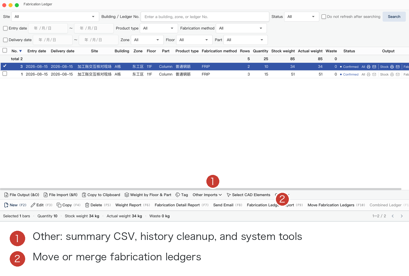
8.4 F2–F12
9. Creating or Editing a Fabrication Ledger
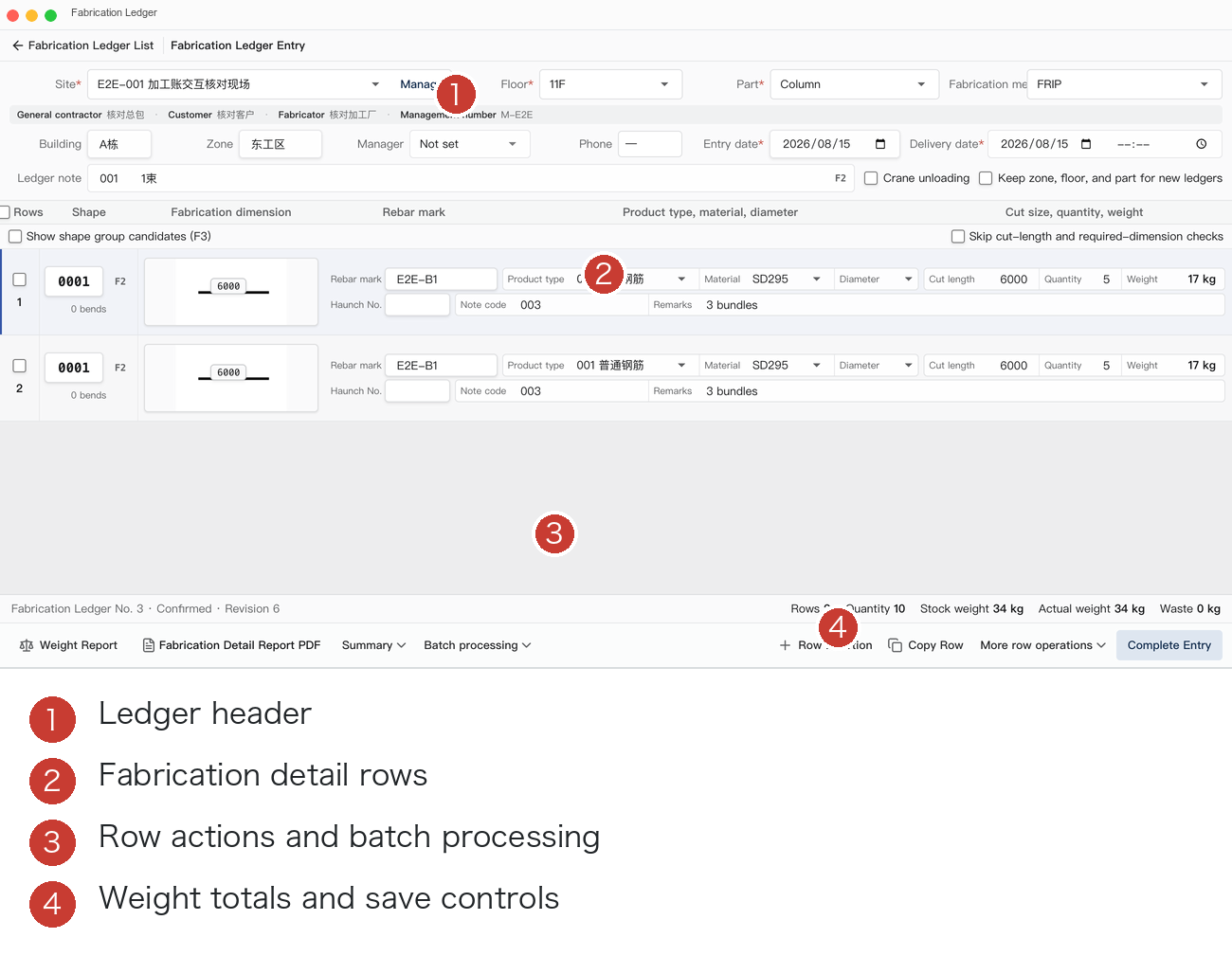
Numbered items: ① Header information (Site, Floor, Part, Dates, etc.), ② Rebar lines, ③ Weight summary, batch tools, line operations, and "Input Complete".
9.1 Header
Mandatory fields are marked with a red asterisk:
- Site
- Floor
- Part
- Fabrication Method
- Entry Date
- Arrival Date
Optional fields include Building, Zone, Manager, Phone, Ledger Remarks, General Contractor, Client, Fabrication Company, and Management ID. Checking "Retain Zone, Floor, and Part on New" allows for continuous entry for the same location; "Crane Unloading" records the arrival method.
9.2 Site Management
Click "Manage" next to Site to open the Site Master Data.
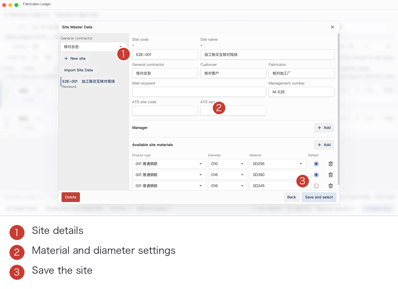
Numbered items: ① Site list, ② Site basic info, ③ Manager and available materials, ④ Save and select.
You can:
- Create, edit, or delete sites.
- Set site codes, names, contractors, clients, fabrication companies, and management IDs.
- Set email recipients, ATS site codes, and versions.
- Add managers.
- Define available grades, diameters, and materials for the site, and set defaults.
- Import site information.
After filling out the form, click "Save and Select" to save and return to the current ledger.
9.3 Fabrication Lines
Each line contains, from left to right:
- Shape: Click the shape ID or press F2 within the line to open the shape list.
- Fabrication Dimensions: Enter millimeter values for A, B, C, etc., based on the drawing.
- Rebar Number: Enter the reinforcement ID from the engineering drawing.
- and 5. Grade, Material, Diameter: Select from the site's allowed range.
- Cut Length: Calculated automatically by the software based on shape and dimensions; for straight bars, use the input length directly.
- Quantity: Enter the number of pieces.
- Remarks Code and Text: Select from remarks candidates or enter custom task notes.
- Weight: The software automatically recalculates stock weight, actual weight, and loss based on current data.
The fabrication ledger calculates weight from the current rows. Changing the shape, dimensions, material, diameter, or quantity updates the totals at the bottom.
9.4 Line Operations
- "Insert Line": Adds a blank line.
- "Copy Line": Copies the current line and allows you to choose the number of copies and destination.
- "More Line Operations": Perform line designation, line clearing, or line deletion on selected lines.
- "Batch Processing": Bulk entry, special calculations, shape conversion, custom drawing, etc.
- "Summarize": Summarize by identical conditions or create a new ledger from the summarized result.
- "Show Shape Group Candidates (F3)": Displays shapes suitable for current conditions.
- "Skip Cut Length/Mandatory Dimensions Check": Only for specific business needs; the page will highlight skipped fields.
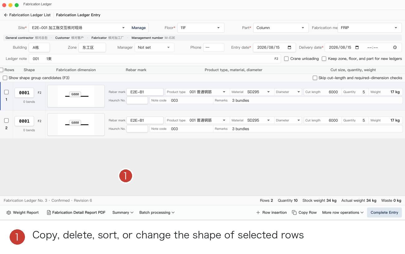
First, select the target lines, then execute the operation from "More Line Operations".
"Batch Processing" centralizes special calculations, bulk input, shape conversion, custom drawing, and expansion. Items that are unavailable will appear grayed out.
9.5 Special Shapes and Calculations
- Shape Replacement: Replacing a shape preserves compatible dimensions; incompatible dimensions are cleared and require re-entry.
- Tapered Sections (Hanchi): Generates gradient data based on endpoints, pitch, and rounding rules.
- ‰ Calculation, Stairs, and Trigonometry: Accessed via "Batch Processing → Special Calculations".
- Custom Shape Drawing: After selecting a custom shape, use a unified drawing window to design a custom fabrication pattern.
9.6 Saving and Completing
The bottom status shows the Ledger No., Draft/Confirmed status, and unsaved changes. Once finished, click "Input Complete". If the header or rows are incomplete, the screen lists the fields that still need attention.
10. Creating a Fabrication Ledger from CAD Canvas
- Open or draw a CAD file containing rebar business data.
- Open the Fabrication Ledger List.
- Click "Select CAD Elements".
- The ledger window temporarily yields focus to the canvas; hold Shift and click one or more rebars.
- The selected count is displayed at the top. "Complete Selection" becomes available after at least one valid object is selected.
- Click "Complete Selection", and the software enters the editor in the original ledger window.
- Verify the site, floor, part, fabrication method, and arrival date.
- Check the imported shape, diameter, material, length, and quantity.
- Click "Input Complete" to save.
Pressing Esc cancels the selection and returns directly to the Ledger List without opening an additional confirmation page.
11. Importing Fabrication Ledgers
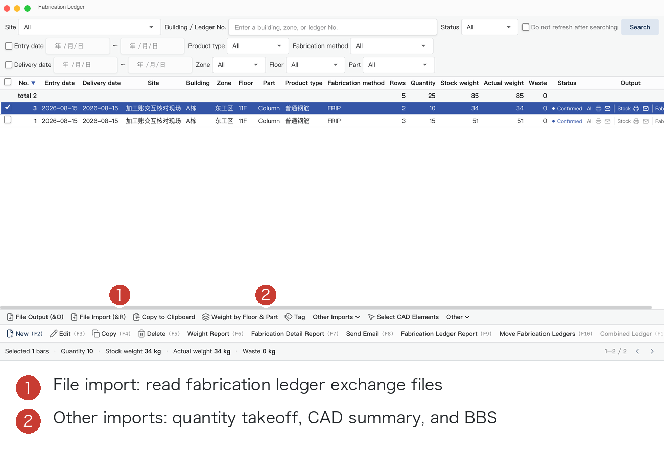
Besides "File Import", takeoff, CAD summary, and BBS imports all enter through "Other Imports".
11.1 File Import
Click "File Import (&R)":
- Select the fabrication ledger exchange file.
- Preview the file, site, master data, and fabrication lines. X. If there are ID conflicts, follow the on-screen prompts to resolve them.
- Confirm to write the entire batch; if one item fails, the entire batch is rejected.
11.2 Takeoff Import
"Other Imports → Takeoff Import" supports CSV/XML takeoff data. Select the site and file, preview the field mapping, correct red-highlighted items, and import.
11.3 CAD Summary Import
"Other Imports → CAD Summary Import" is used to import CAD summary tables. Red cells must be corrected; special values (e.g., fabrication method 95–99) must be mapped to their meanings via the interface before grouping and writing.
11.4 BBS Import
"Other Imports → BBS Import" reads BBS rebar data and provides a preview. Confirm shape, dimensions, grade, material, and diameter before writing to the current site.
12. Reports, Tags, Email, and File Exchange
12.1 Reports
- Weight Table: Statistics for stock, actual, and loss weights.
- Floor/Part Weight: Summary by floor and part.
- Fabrication Detail List: Individual production details.
- Ledger List Report: List report for selected tasks.
- Shape Map: Catalog of shape master data.
Reports support paginated previews and can be exported as CSV, HTML, Excel, printed, or saved as PDF. Options allow controlling column visibility, quantity overrides, and custom shape appendices.
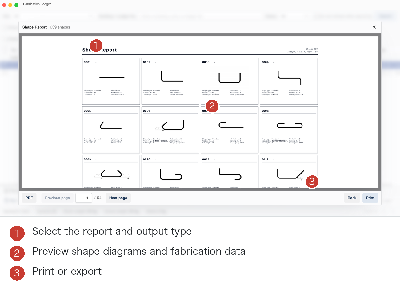
Numbered items: ① Preview of shape, fabrication method, and cut length formula, ② Pagination, PDF, and print operations.
12.2 Tag Cards
Click "Tag Card":
- Select a 5-part or 10-part layout.
- Check site, floor, part, rebar number, size, quantity, and shape.
- Generate QR codes and borders as needed.
- Preview, flip pages, and print or save.
After successful output, the "Output" column in the list shows the corresponding status.
12.3 Email
Select a confirmed ledger and press F8:
- Choose recipients and subject/content.
- Verify arrival date, site consistency, and attachments.
- Sending is unavailable when a ledger is unconfirmed, has no recipient, spans multiple sites, exceeds quantity limits, or uses an unsupported shape.
- After sending, you can view the email history and resend status.
12.4 Site Output and File Output
- File Output: Exports selected ledgers as exchange files for backup or transfer.
- Site Output: Exports all ledgers and master data for a specific site.
- File Import: Restores exchange files.
- Shape Master Data Export/Import: Shape ZIP, CSV, and calculation rule INI files can be imported after preview.
13. Master Data and Options
Entry: "Ledger List → Other → Master Data, Options".
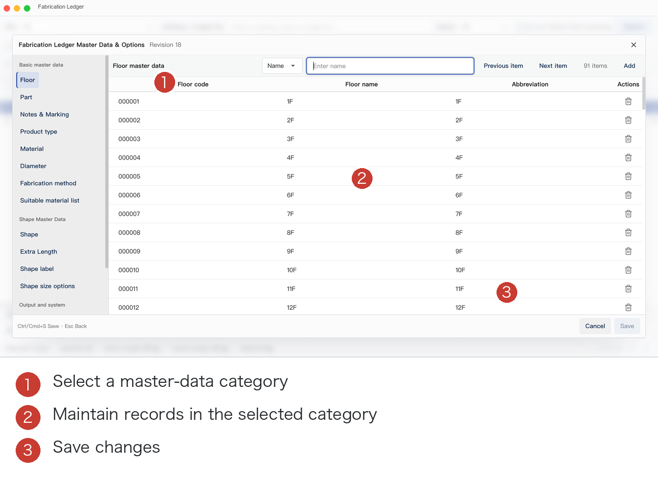
Numbered items: ① Master data categories, ② Search and Add, ③ Current category data table, ④ Save entry.
13.1 Basic Master Data
- Floor
- Part
- Remarks, Marks
- Grade
- Material
- Diameter
- Fabrication Method
- Material Suitability Table
Supports adding, deleting, searching, and managing codes. The suitability table defines which stock lengths and calculation ranges apply to specific sizes.
13.2 Shape Master Data
- Shape
- Allowance
- Shape Label
- Shape Dimension Options
- Formulas, Auxiliary Lines, and Custom Drawings
- Shape Import, Export, and Restore
Master data currently referenced by business data cannot be deleted; please remove all references first.
13.3 Output and System
Settings include rules for input, suitability, report columns, tag card layouts and colors, calculation rules, email configuration, etc. Only one effective configuration is kept for each purpose to avoid maintenance confusion.
14. Ledger Management
14.1 Moving
Select a ledger and press F10, then choose the target site and confirm. After moving, the ledger uses the effective master data of the target site; the move is blocked if conditions are not met.
14.2 Merging
Select multiple ledgers meeting the criteria and press F11. Review the merge preview before confirming; merging is blocked if sources are inconsistent or conditions are not met.
14.3 CSV Summary
Press F12 to select a range and create a CSV. The CSV uses a fixed column order and encoding, making it suitable for transfer to other production systems.
14.4 History Cleanup
"Other → History Cleanup" is used to delete historical data. Select the site and criteria, review the expected impact, and then execute; data currently referenced by business operations will not be deleted.
15. Settings and Updates
Click the gear icon in the top right of the main window:
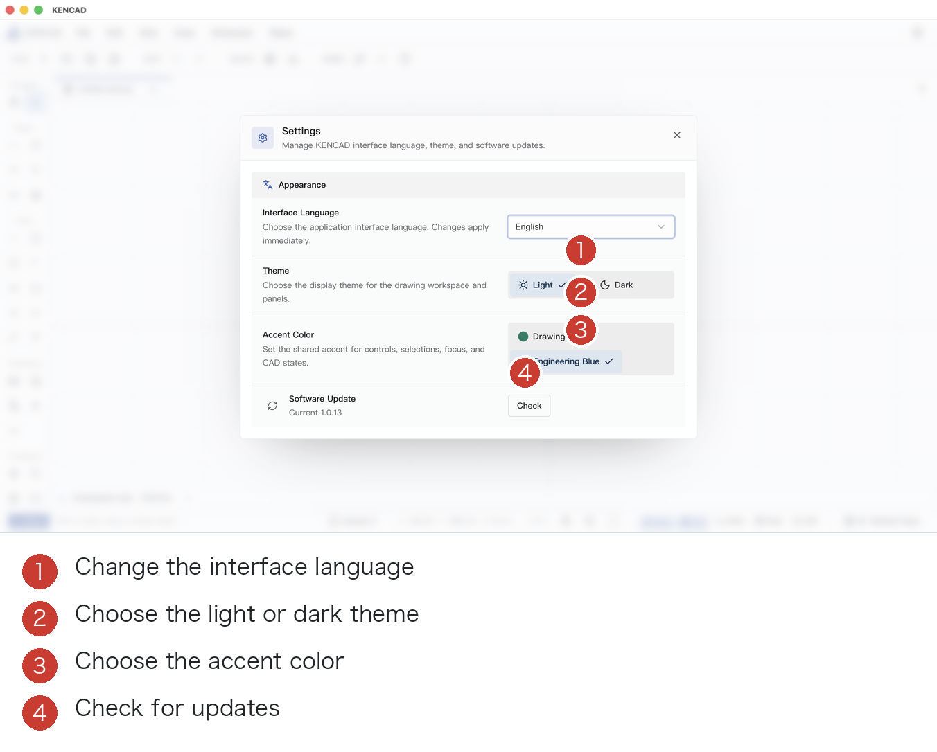
- Interface Language: Simplified Chinese, English, Japanese, Tiếng Việt.
- Display Theme: Light or Dark; changes take effect immediately.
- Theme Color: Drawing Green or Engineering Blue; affects buttons, selection states, focus, and CAD operation status; the engineering colors of the drawing itself are not altered.
- Apply Updates: View version and update status.
The fabrication ledger and main workspace use the same language and theme.
16. Common Shortcuts
| Shortcut | Function |
|---|---|
| Ctrl/Cmd+N | New Drawing |
| Ctrl/Cmd+O | Open Drawing |
| Ctrl/Cmd+S | Save Drawing |
| Ctrl/Cmd+Z | Undo |
| Shift+Ctrl/Cmd+Z | Redo |
| Ctrl/Cmd+C / X / V | Copy / Cut / Paste |
| Ctrl/Cmd+D | Duplicate Object |
| Delete/Backspace | Delete object; undo last point during input |
| Esc | Exit command, close task, or cancel CAD selection |
| Enter/Space | Complete continuous point selection |
| H / V | Pan Canvas / Select |
| L / R / C / A | Line / Rectangle / Circle / Arc |
| P / PL / T | Polyline / Text |
| M / S / O | Move / Scale / Offset |
| F2–F12 | Corresponding functions in Fabrication Ledger |
| F1 or Command Line ? | Open KENCAD Help |
17. Shortest Onboarding Route for New Users
Route A: Manually Creating a Fabrication Ledger
Ledger List → F2 New → Manage Site → Fill Floor, Part, Method, and Date → Select Shape → Enter Dimensions, Rebar Number, Grade, and Quantity → Check auto weight → Input Complete → F7 Output Detail List.
Route B: Creating a Ledger from CAD Rebar
Open CAD → Confirm Rebar Data → Ledger List → Select CAD Elements → Shift+Click rebar → Complete Selection → Fill Header → Input Complete → Output Report.
Route C: Creating Beam Reinforcement from Design Drawing
Open Design Drawing → Capture Structure/Beam → Select and derive template from original geometry → Clean → Pick supports and spans → Configure Main/Stirrup Bars → Writeback CAD → Cutting List → Fabrication Ledger.
Route D: Modifying and Plotting CAD Only
Open Drawing → Select/Draw/Edit/Annotate → Check Layers → Save → File/Export → DWG, DXF, PNG, or Plot PDF.
18. Frequently Asked Questions
Why can't I output the fabrication detail list?
Check the site, floor, part, fabrication method, and delivery date, plus the shape, dimensions, size, and quantity on each row. The screen lists any missing fields.
Why is a certain shape grayed out?
It does not match the current product type or fabrication method. Adjust the filters and select an available shape.
Do I need to manually recalculate the weight?
No. The fabrication ledger automatically updates weights using the same calculation path whenever data changes.
Will my data be lost after closing?
The software prompts for confirmation if there are unsaved changes in a drawing. For the fabrication ledger, the bottom status shows Draft/Confirmed and unsaved status; click "Input Complete" after finishing entry.
What should I do if an error occurs?
Keep the original error message and current file. First, attempt to complete the data as prompted. If you still cannot proceed, record the entry point, filename, and error message, then contact technical support.
19. Data Security Recommendations
- Keep read-only copies of original design drawings.
- Save drawings after completing each key stage.
- Verify rebar number, grade, size, length, and quantity before formal production.
- Preview reports or tags before external transmission.
- Periodically back up ledgers using file output; preview data before restoring via file import.
- If a production value is unclear, check the source drawing instead of filling the field with an estimate.
No section contains that search term.